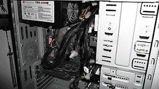
POWER SUPPLY UNIT-SMPS (SWITCH MODE POWER SUPPLY)
The most common computer power supplies are built to conform to the ATX form factor. This enables different power supplies to be interchangeable with different components inside the computer. ATX power supplies also are designed to turn on and off using a signal from the motherboard, and provide support for modern functions such as the standby mode available in many computers. The most recent specification of the ATX standard PSU as of mid-2008 is version 2.31.
Note that some manufacturers, most notably Compaq and Dell, have produced power supplies using the same connectors as ATX but with different voltages on different pins; mismatching such PSUs and motherboards can result in damage to either or both


PC Main power connector (usually called P1): Is the connector that goes to the motherboard to provide it with power. The connector has 20 or 24 pins. One of the pins belongs to the PS-ON wire (it is usually green). This connector is the largest of all the connectors. In older AT power supplies, this connector was split in two: P8 and P9. A power supply with a 24-pin connector can be used on a motherboard with a 20-pin connector. In cases where the motherboard has a 24-pin connector, some power supplies come with two connectors (one with 20-pin and other with 4-pin) which can be used together to form the 24-pin connector.
ATX12V 4-pin power connector (also called the P4 power connector). A second connector that goes to the motherboard (in addition to the main 24-pin connector) to supply dedicated power for the processor. For high-end motherboards and processors, more power is required, therefore EPS12V has an 8 pin connector.
4-pin Peripheral power connectors (usually called Molex for its manufacturer): These are the other, smaller connectors that go to the various disk drives of the computer. Most of them have four wires: two black, one red, and one yellow. Unlike the standard mains electrical wire color-coding, each black wire is a ground, the red wire is +5 V, and the yellow wire is +12 V. In some cases these are also used to provide additional power to PCI cards such as FireWire 800 cards.
4-pin Berg power connectors (usually called Mini-connector or "mini-Molex"): This is one of the smallest connectors that supplies the floppy drive with power. In some cases, it can be used as an auxiliary connector for AGP video cards. Its cable configuration is similar to the Peripheral connector.
Auxiliary power connectors: There are several types of auxiliary connectors designed to provide additional power if it is needed.
Serial ATA power connectors: a 15-pin connector for components which use SATA power plugs. This connector supplies power at three different voltages: +3.3, +5, and +12 volts.
6-pin Most modern computer power supplies include 6-pin connectors which are generally used for PCI Express graphics cards, but a newly introduced 8-pin connector should be seen on the latest model power supplies. Each PCI Express 6-pin connector can output a maximum of 75 W.
6+2 pin For the purpose of backwards compatibility, some connectors designed for use with PCI Express graphics cards feature this kind of pin configuration. It allows either a 6-pin card or an 8-pin card to be connected by using two separate connection modules wired into the same sheath: one with 6 pins and another with 2 pins.
A C14 IEC connector with an appropriate C13 cord is used to attach the power supply to the local power grid.

There are two basic differences between AT and ATX power supplies: The connectors that provide power to the motherboard, and the soft switch. On older AT power supplies, the Power-on switch wire from the front of the computer is connected directly to the power supply.
On newer ATX power supplies, the power switch on the front of the computer goes to the motherboard over a connector labeled something like; PS ON, Power SW, SW Power, etc. This allows other hardware and/or software to turn the system on and off.
The motherboard controls the power supply through pin #14 of the 20 pin connector or #16 of the 24 pin connector on the motherboard. This pin carries 5V when the power supply is in standby. It can be grounded to turn the power supply on without having to turn on the rest of the components. This is useful for testing or to use the computer ATX power supply for other purposes.
AT stands for Advanced Technology when ATX means Advanced Technology eXtended.
 24-pin ATX12V 2.x power supply connector(20-pin omits the last 4: 11, 12, 23 and 24)

Comments
Post a Comment